Introduction
Figure 1
Figure 2
A transverse slice of the CMS detector and the
particles detected by each subdetector.
Tracker detector
Figure 1
Figure 2
A schematic of a pixel detector.
Figure 3
Silicon strips in the tracker barrel.
Figure 4
A projected event display view of the CMS
tracker (contained within the ECAL barrel and endcaps) looking
perpendicular to the beam pipe.
Figure 5
![]() |
| ![]()
Figure 6
![]() |
| ![]()
Electromagnetic Calorimeter (ECAL)
Figure 1
Figure 2
Lead tungstate crystals. One can see an APD
attached to the end of one of the crystals at the bottom of the
image.
Figure 3
 |
| 
Hadron Calorimeter (HCAL)
Figure 1
Figure 2
A schematic view of the HCAL detectors, looking
“from the side”, perpendicular to the beam pipe.
Superconducting magnet
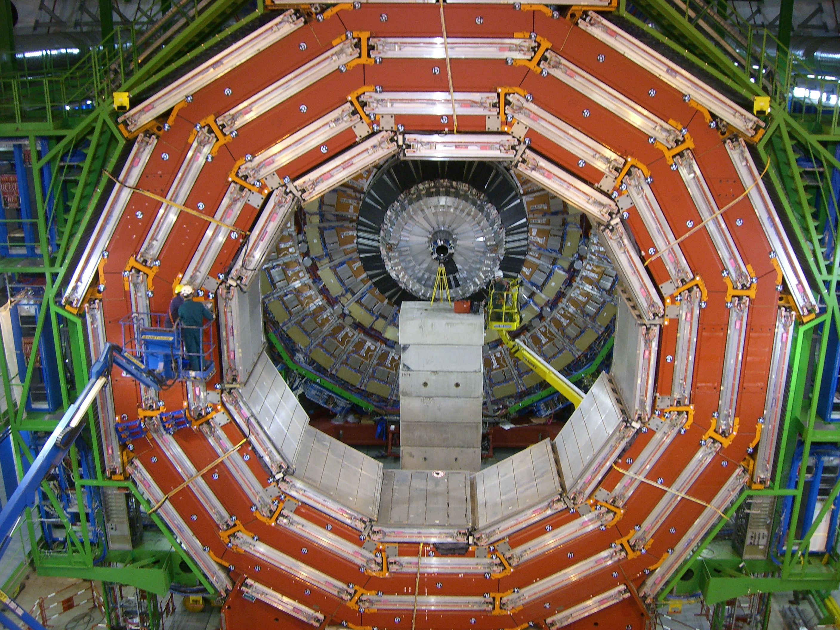
Figure 1
Muon detectors
Figure 1
Figure 2
A transverse slice of CMS slowing a muon passing
through RPCs and DTs in the barrel.
Figure 3
 |
| 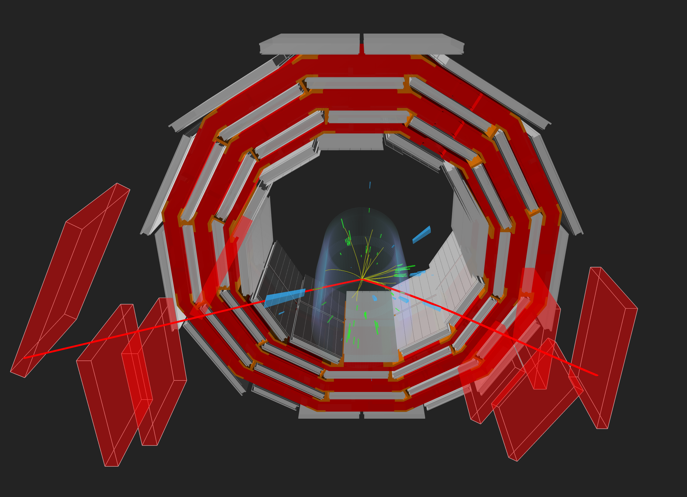
Figure 4
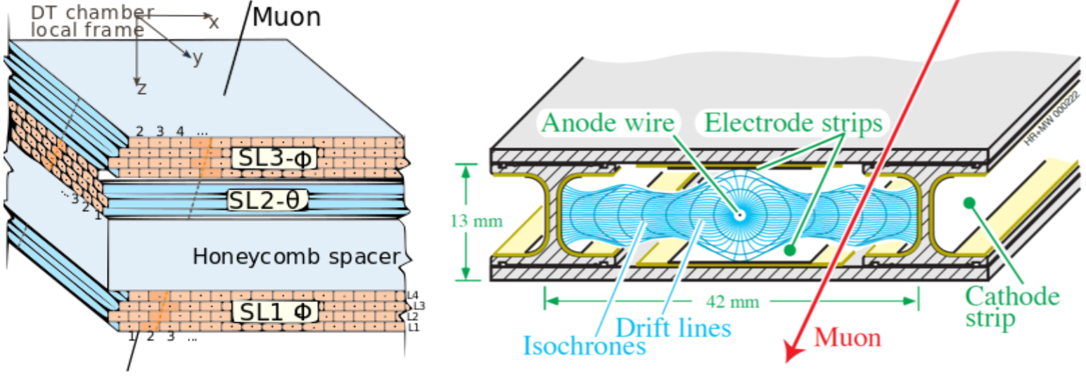
Figure 5
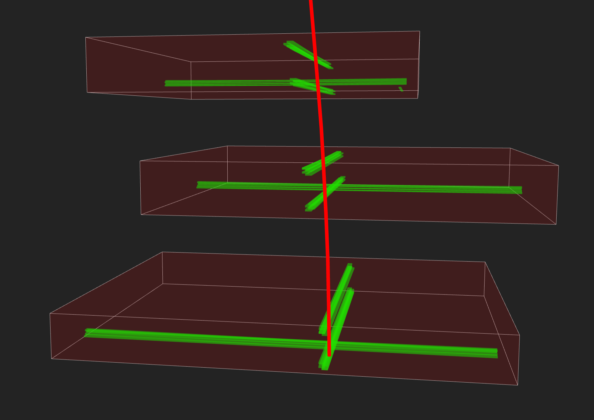
An event display of a muon seen in DTs. The
green volumes indicate the position of the triggered wires.
Figure 6
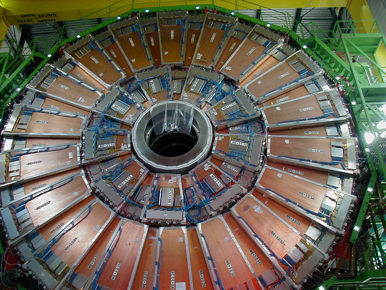
Installed CSCs.
Figure 7
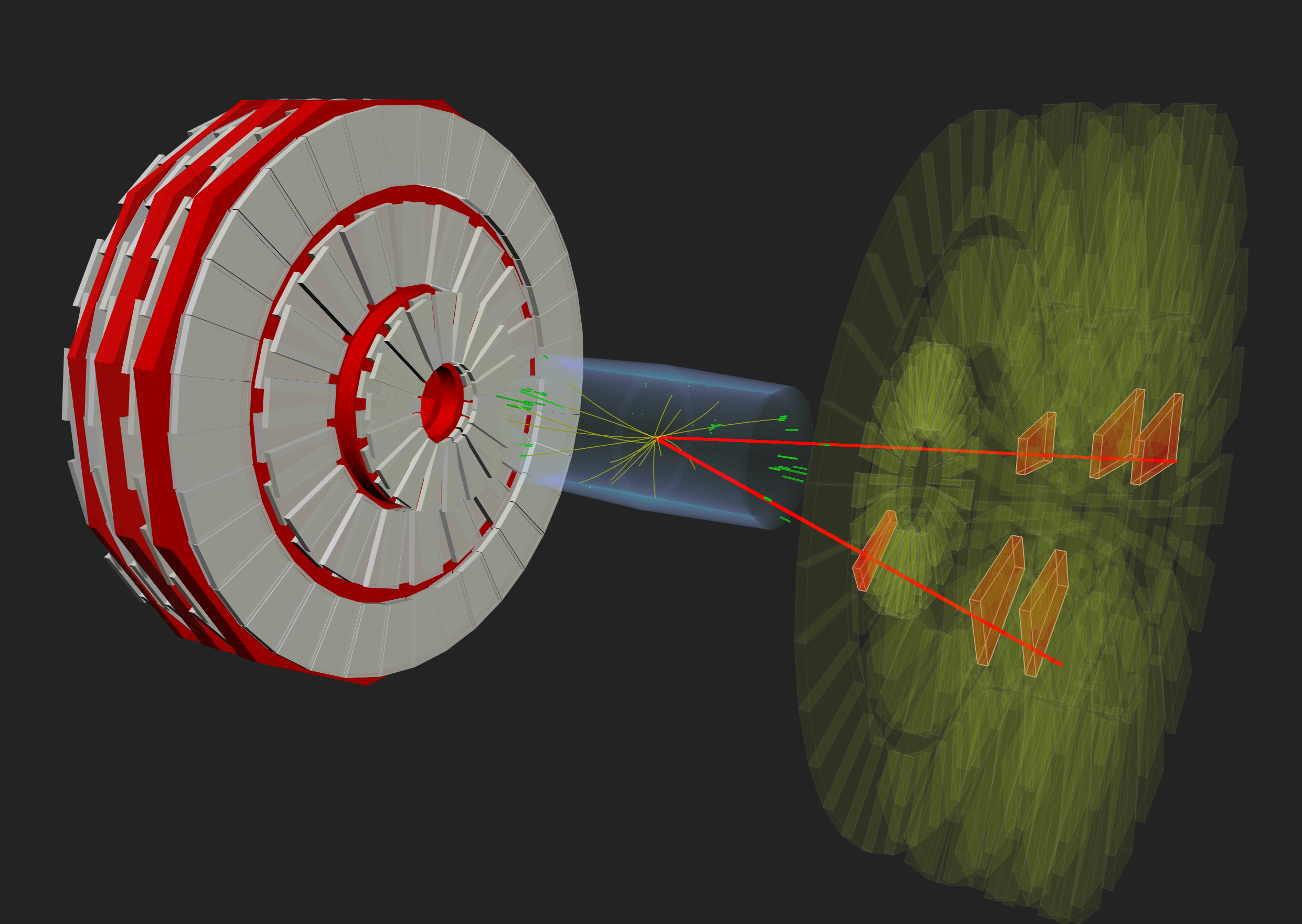
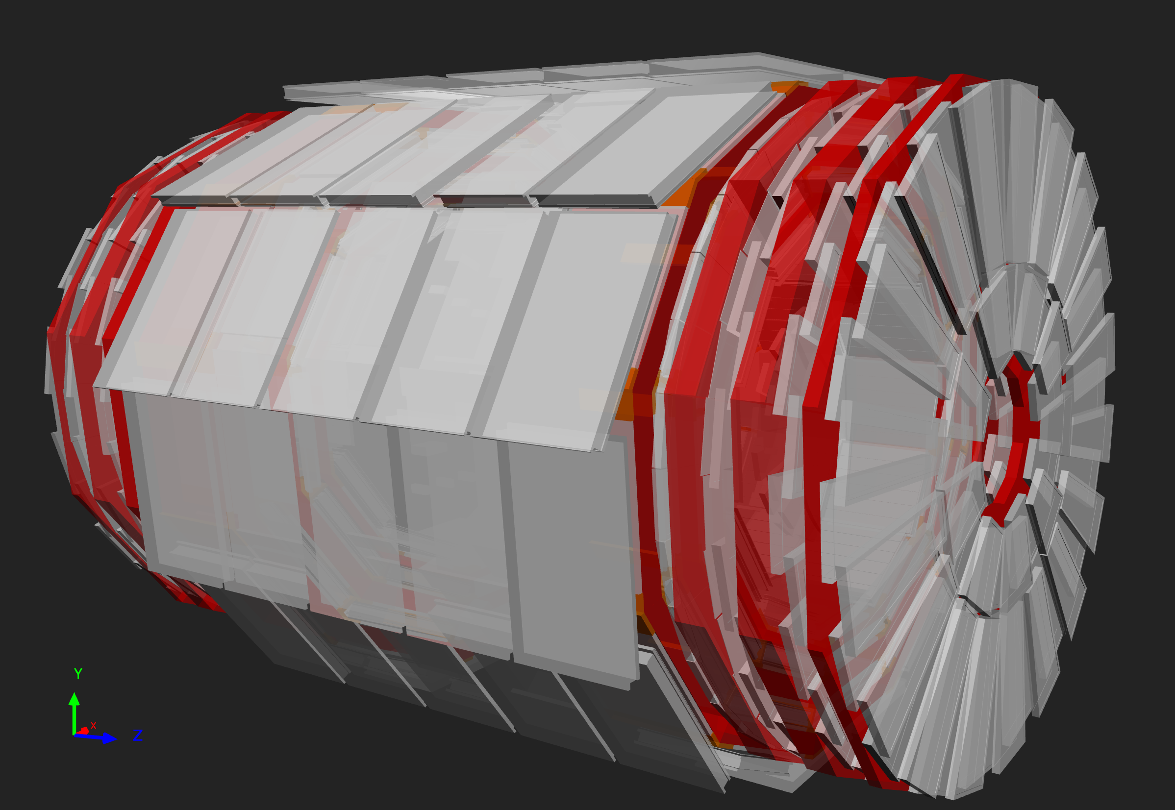
A double muon event seen in CMS with highlighted
matching CSCs (in red).
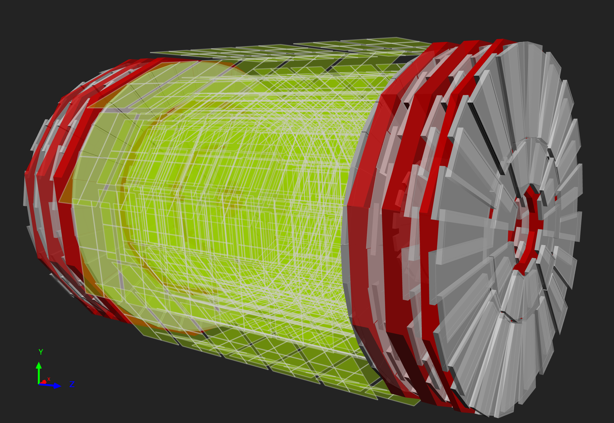
Figure 8
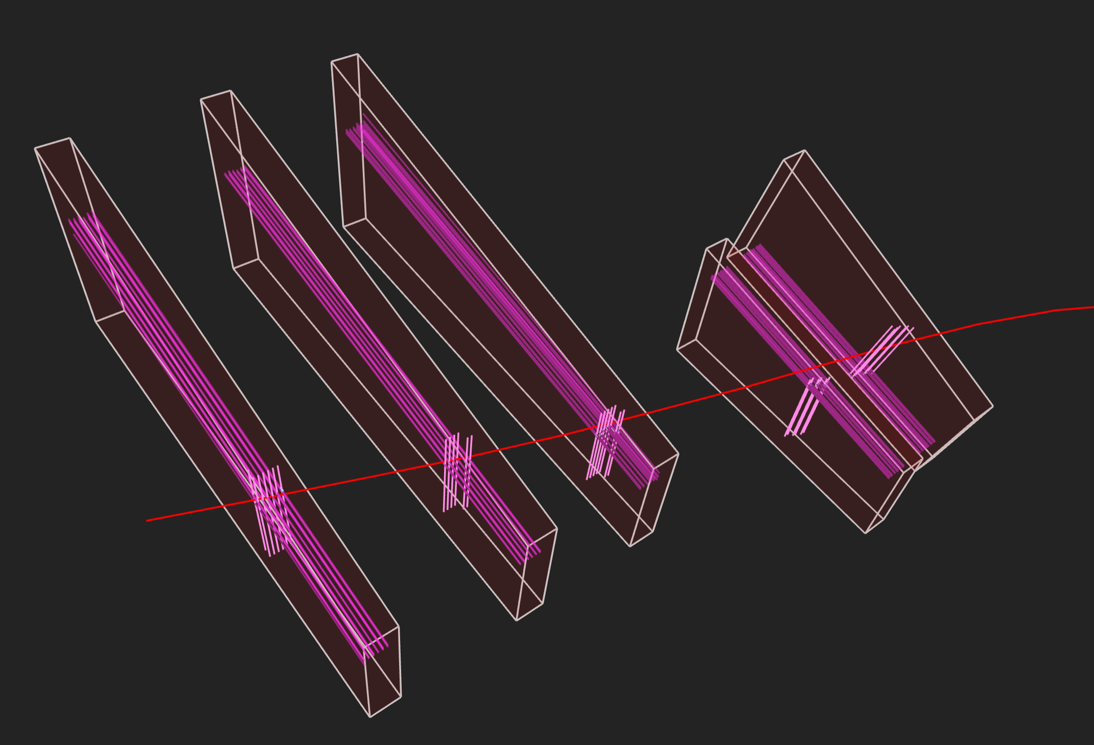
Event display of a muon seen in CSCs. The pink
lines running along the long end of the chambers indicate the triggered
strips and the shorter pink lines represent the triggered wires.
Figure 9
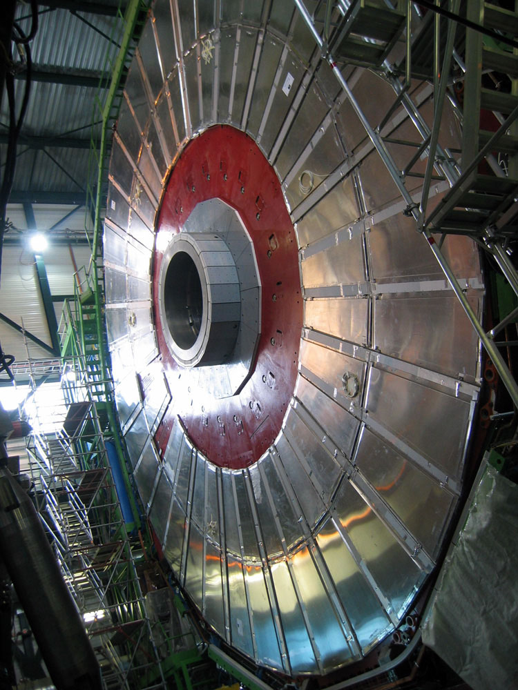
Resistive plate chambers installed on one of the
CMS muon endcaps.
Figure 10
 |
|  |
| 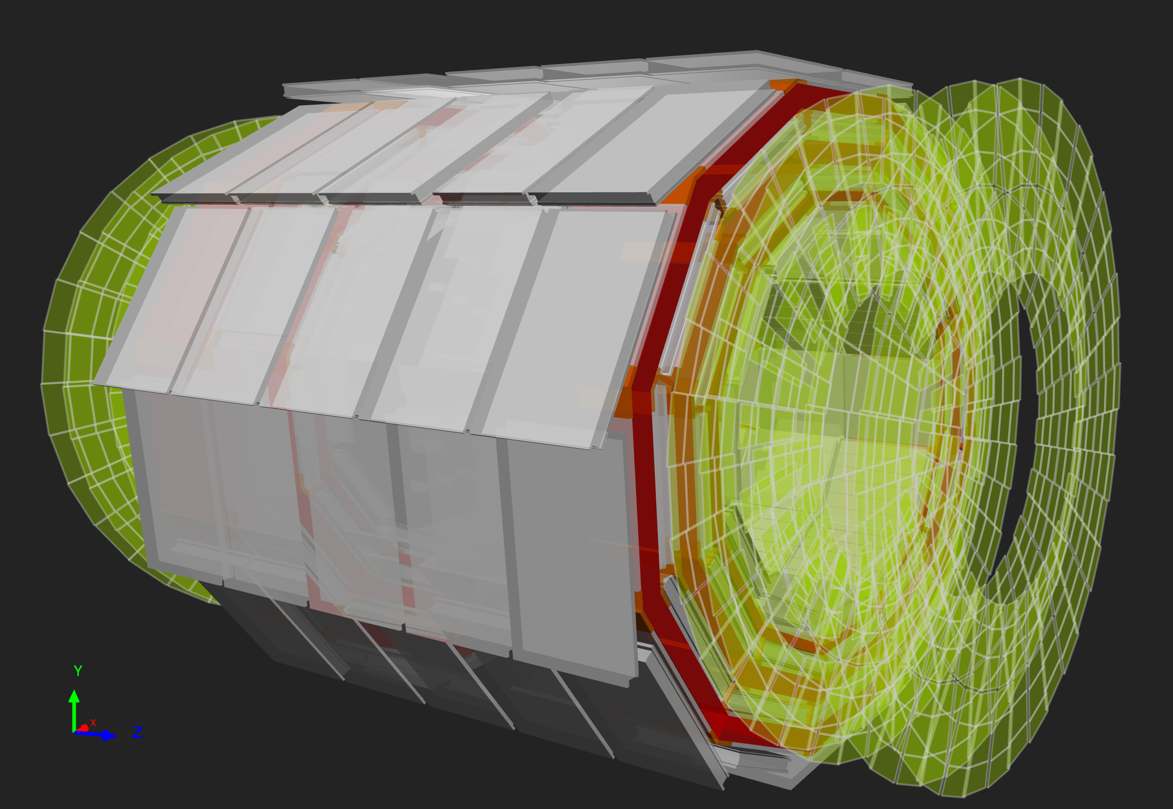
Figure 11
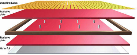
The layers of an RPC